
Motor Mount Replacement and Engine Alignment on a Gemini 105 with the Westerbeke 30B Engine
Sailing Vessel Freedom - a Gemini 105 - Jim and Deb Faughn
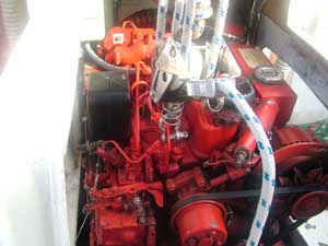
March 8, 2007 - Note: This is a long description and at the end I hope you will understand the history, the process I used, and be able to accomplish this yourself if you have mechanical skills. I have had a vibration, which most have said was minor and is typical of all diesels, when the engine is running at cruise speed (2600 rpm) since I have owned the boat. Since this was my first diesel, I didn't know any difference. In addition, since the motor has 1900 hours on it, I haven't had any problems that can be directly attributed to the vibration. However, since a posting on the Gemini list serve about engine alignment back in about July, I have wondered if my engine should be aligned. We began our cruising life after moving aboard in September and leaving October 15, 2006 on the date we set. I spoke with a number of people as we have cruised from Kentucky Lake to where I ultimately took on this project in Key West at anchor. Their advice primarily was, if it hasn't created a problem by now it isn't a problem, don't worry about it. I'm one of those people that have to have things working properly or I research it and fix it. With that introduction, as we were looking at moving north this spring and early summer to the Chesapeake, I decided it was time to make the checks and do the alignment. When I went through the procedure to align the engine, which I will post below, I found the alignment was out. I was unable to get the horizontal closer than 8 thousandths so I decided I needed to remove the forward mounts and elongate the holes so I could get more adjustment. When I took out the mounts, I found they were not in new condition. They had rust, the rubber had delaminated, the retainer cap was misaligned and overall I thought they were weak. I took them to two friends here in Key West who are also at anchor. The first person has a vast array of experience, after rebuilding several boats and living on a boat for the last 25 years and a person I respect, he thought they should be replaced. The second person happens to be a Yanmar Distributor in Canada so he should know about engines, he also agreed that they weren't totally bad but need to be replaced. So, it seemed my judgment was correct. I then tried to find the mounts locally and fortunately I was not able to find them based on the part numbers in our Westerbeke 30B parts list. Looking through my paperwork, I ran across a phone list of people at Engines 1. I had met one of the people last year at the Miami Boat Show when I was considering quitting my job and going cruising. He treated me with great respect and went to a 30B engine and talked me through a number of the most common problems people encounter and gave me a list of maintenance items which should be performed. With that background, I called and talked to their parts manager. I'll leave his name out because I'm sure all of their parts people can help. However, the phone number for Engines 1 is 757-673-7200. They told me that they DID NOT use the motor mount numbers which are listed in the parts manual included with all of the Gemini's. Instead, to get the engine to fit properly in the space, they had to use a different motor mount or in their words - engine isolator assembly. I have to tell you, was I very happy I called them. It seems that not many motor mounts go out so they had to get the mounts shipped to them from the factory and then 2nd day air to me. All of this was to occur within 5 days when I should receive them in Key West. Guess what? It happened exactly as I was told! I love customer service and I have to say this was excellent service. I hereby highly recommend the people at Engines 1 which I found is a subsidiary of Western Branch Diesel, Inc. By the way, the correct Westerbeke numbers for our motor mounts are - 36339 for the front mounts (alternator end) and 36340 for the rear mounts (transmission end.) I think everyone should change these numbers in their parts book if you own a Gemini. I hope you never have to change them but the below will help if you do. I also gave Performance Cruising a call and talked to Will about replacing the mounts and aligning the engine. Will took the time to go out on their factory floor and create a video with their mechanic explaining how he would change the motor mounts. As you will see, I used a bit different technique because I am at anchor but their technique would be easier if you have the equipment. He sent me the link to the video and was also very interested in why I thought the motor mounts were bad. I am certain he and the company were trying to learn more about their boats. My Gemini is now 11 years old and is hull number 536. In addition, it has 1900 hours on the engine. After receiving the ling for the video, I found it to be of assistance even though I used a different technique for replacement. There are many tips in the video which proved helpful. Again, I found that Will and thereby the people at Performance Cruising were very helpful to help me. By the way, I sent him pictures which you will see below, and his opinion was the mounts were "toast." Again, I felt better that I had used the proper judgment. The bottom line is I have had great service from Performance Cruising and appreciate the assistance. With all of that as background, I hope you will find the descriptions and pictures below as helpful. If you see anything you have questions about, please email me so I can either correct the descriptions or make them more understandable. |
|
I mentioned that Will made a short video for me. He gave me permission to provide the link so you can also view the video. I recommend you watch this first before going through the process I used. The pictures provide a complete picture of the engine which you won't see with it mounted in the engine box. In addition, they have provided many tips. You will have to decide if you want to pull the engine or do it the way I did. |
Will's video from Performance Cruising |
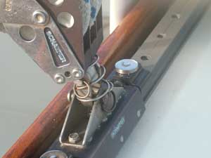
I started my process by attaching the main halyard to the shackle at the end of the boom to provide additional support to the mast. I didn't want to just trust the outhaul to hold up the front of the engine even though I'm sure it would have done so. It only took a few minutes to also put on the main halyard which provided a degree of confidence. I then placed two lines from the mast down to the cleats on each side of the boat to ensure the boom would not move when waves came by at anchor. In the picture to the right, you can see the pin I removed which holds the mainsheet to the car on the traveler. The pin and the ring hold the sheet in place. |
 |
 |
Next I used a shackle to attach the main sheet to the engine on the lift point provided by Westerbeke. I used this to remove the weight from the motor mounts and it allowed me to remove the brackets which you will see below while supporting the engine. Again, I am at anchor and everything we own is on the boat so I don't have things such as jacks or other items people may have with a shop at home. I'm not complaining, it is actually fun to figure out how to accomplish a project with the equipment we have. Call me a cruiser... |
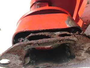
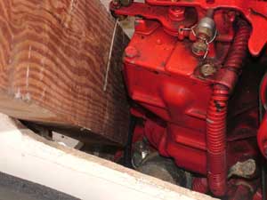
This is a picture of the port side motor mount. You can see it is going to be tight to get it out. You will need a 9/16 wrench to loosen the bolts holding the mount to the engine bed. Of course by this time you will have removed both of the access panels on each side of the engine. The rear bolt on the front mounts have to be loosened one flat at a time so you need an open ended wrench that is the right length. the front bolts can be removed with a socket wrench but you need a minimum of a 16 inch extension. You will also need a 15/16th wrench to loosen the adjusting nuts which are on the mounts. I ended up going to Sears (3 miles each way bike ride) and buying a stubby wrench. This stubby wrench worked perfectly. Be careful and at this time and only loosen the top locking nut. You don't want to move the lower nut at this time. The reason is that this will be what you look at to get you new mounts into approximate alignment. |
 |
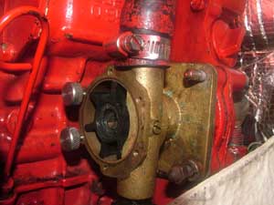 |
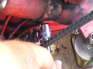
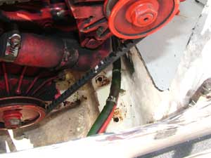
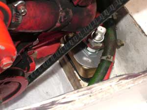
On the starboard side, I found it very difficult to get to the rear bolt holding down the starboard forward mount. I also needed to loosen the rear mounts for the adjustment. Therefore, I removed the hose going into the bottom of the raw water pump and then I removed the water pump itself. The nuts are 12mm nuts and you can remove 3 with a small socket wrench. The bottom one to the starboard side I had to finish up with a wrench. Of course when you remove this pump, you may need a new gasket for the water pump. I ordered a new gasket just in case, which I didn't have to use, when I ordered the mounts. |
| This picture shows the water pump removed and out of the way. | 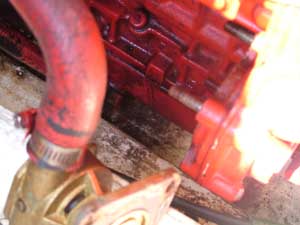 |
 |
In the Westerbeke book, it shows some drawings which identify the brackets mounted to the engine which they attach the motor mounts. This picture actually shows me putting the bracket back on but taking it off looks the same. The socket size is 11/16ths and I am using a 3 inch extension on a 3/8ths socket wrench. There are two bolts holding the mounts to the engine. You should first loosen the bolts a little on each side and then take up any slack on the mainsheet. You can pull the sheet by hand and get the engine weight off of the mounts and brackets. At this time you can remove the two bolts on each bracket. Caution. Getting the port bracket out with the motor mount on is easier than the starboard bracket. I pulled the port bracket down, twisted it and out the port access panel. I pulled the starboard bracket and mount down, twisting and then up past the front of the engine. Here is the caution, when removing the starboard mount I neglected to see the oil pressure switch and broke off a terminal. Therefore I had to call Engines 1 back and they added on a new oil pressure switch to my order. |
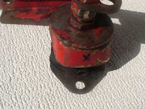
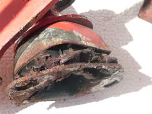
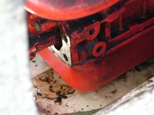
| I think you will agree the mounts don't look to good. However, I must say, as you can see in the picture in the center below, they still have rubber on the sides of the metal container. Comparing them to the new ones, they were definitely weaker. | 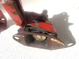 |
   |
|
 |
This view shows the port side of the engine with the bracket removed. the silver part is where I removed the bracket and you can see the two mounting holes for the bracket to hold the engine mounts. By the way, when you are being timid about doing this project, take a small mirror and look at the bolts. If you are like me and more visual than tactile then the view from the mirror will be worth the effort. You can also see that I am cleaning up the bottom of the engine because after 11 years of not being able to reach in, this is as good of a time as it gets. |
| This view shows the starboard side and you can actually see the rear mounting hole below the oil fill plug that none of us use. Again, I took time to clean up the rust from this area so the engine would slide easier when I was aligning the engine. |  |
| This is another view from the starboard side and this time you can see both the forward and rear mounting holes. | 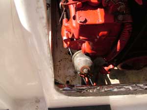 |
 |
And of course I couldn't slight the port side. I don't know at this point if I was trying to show something or I was proud of the fact that it was cleaning up so well. Just in case you are wondering and if anyone actually reads this, when cruising a sense of humor is good especially if you are actually trying to change motor mounts while anchored 2 miles off of Key West. |
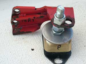
This is actually a great picture. My reason is you can see the bracket that is attached to the engine that you are removing and you can see the new motor mount. When you install the mount to the bracket, it is very critical to make sure you have marked the port and starboard motor mounts. Since the new mounts will come with the nuts installed but nowhere near where they should be, this is your opportunity to count the threads up from the nut by the washer on the old mounts and then set the new mounts the same number of threads up. By doing this on the port and starboard side, you get very close on the alignment. The other thing you can see, which invalidated my warranty on the mounts, is that I elongated the hole for adjustment. I had to do this because I needed to get the engine further to port on the front end to get it into alignment. This is just my problem, don't do this unless you are absolutely sure you must. |
 |
|
Now I am reinstalling the brackets with the motor mounts attached. I'm getting pretty happy at this point because I will soon have a working engine again. After installing both brackets and installing the bolts for the motor mounts to the engine engine bed without tightening them completely down, I was ready for engine alignment. |
| At this point I would like to reprint the post from Tom Jessop about aligning the engine. After all, it was Tom that got me thinking about this in the first place and I like to give credit where it is due. I followed his procedure and will show a couple of pictures relevant to the procedure along with some of my explanation following the reprint. Here's the deal on
the alignment. First the westerbeke and the top of the flexible coupling
need to be the same angle to the horizontal, that is 7 degrees. I bought
a Home Depot angle measuring device. It is magnetic and reads out on a
dial. First I measure the coupling putting the gage across the plates
of the coupling. Then I measure the motor angle putting the gage on the
rocker cover. Measuring the angle of the coupling and then of the motor
lets you know if you need to change the angle of the motor by running
the nuts on the motor mounts up or down. The nuts are 15/16 in. and I
used a crow foot on them so that I could hold the flat threaded rod like
section while turning the nut to raise the motor. The coupling has opposed
bolt heads that have a space between them. With the bolt head pair rotated
to starboard use feeler gages to measure the space between the bolt heads.
With the transmission in neutral, manually rotate the same two bolts to
port. Measure the space with feeler gages. If the space is the same as
it was on starboard the engine and coupling are angularly aligned horizontally.
If the space is different by .005 in. or more the engine has to be shifted
angularly in the horizontal plane until the space between the bolt heads
port then starboard are within .005 in. Next, using the bolts in the top
position measure the space between the heads. Manually rotate the coupling
180 degrees to bring the same bolts to the bottom position. Measure the
distance between the heads. If different from the top spacing by more
than .005 in. the angle of the transmission and engine needs to be adjusted
in the vertical plane by moving the nuts on the motor mounts. I used a
2x4 section to jack the engine around taking the weight off the nuts as
I rotated them up. I used my calipers to make sure that the engine mounts
port and starboard were kept an equal distance above the floor to make
sure that the engine was vertical as I jacked up the front of the engine
to get It's angle to the coupling correct. I found it easy to move the
engine by prying with a length of 2x4. Once readings between the bolt
heads are the same top to bottom and side to side lock down the engine
mounts and remeasure. It's belly work reaching down into the rear hatch
but it's not too demanding. I removed the exhaust loop to make access
and angle measurement easier. I have a modified low clearance exhaust
loop. The standard on may not need to be removed. My engine was vibrating
at the start of this year and one full turn on the engine mount nuts smoothed
it right out. Vibration in gear and out of gear should be about the same
if the alignment is close. The smoother it is in gear the less you are
beating up seals and bearings. Let me know how you make out. |
|
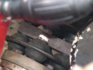
The picture to the right shows the coupling between the transmission and the outdrive. I marked one of the bolt heads with some white out just so I would ensure I used the same bolt head pairs when doing the alignment. Basically, I measured between these two bolt heads at the 0 degree, 90 degree, 180 degree and 270 degree positions with a feeler gauge set. Another way to express this is at the 12, 3, 6, and 9 o'clock positions. Of course the measurements are critical and you are comparing the 0 with the 180 for vertical alignment and the 90 with 270 degree for the horizontal alignment. The reason to only use one bolt head pair is these are not manufactured to precision so if you don't use the same bolt head pair then you will not have accurate measurements. As Tom mentioned previously, you need to be within 5 thousandths vertically and horizontally to ensure alignment. Mine aligned to 2 thousandths vertical and 3 thousandths horizontal. |
 |
 |
Here you can see a great tool. The 2 x 4. The engine doesn't want to move very easily in the horizontal direction. So, all you have to do is go by a construction site, talk real nice and get a 3 foot 2x4 to use for leverage. My wife, Deb, was able to hold it as I tightened down the engine mount bolts and I got a good alignment. Of all of the things on this project, this is the only two person job. |
This is success. New motor mounts installed at the forward of the engine. The vibration is gone and the engine really doesn't move when at 2600 rpm. The project was worth it and many people couldn't believe I did it at anchor. The reality is that I did it twice. The first time I pulled out the motor mounts to check them and then had to put it all back in because a storm front was coming and you don't want to be at anchor without an engine. the second time was easier. I hope, if you use need to do this, that your first time will be by reading the description and looking at the pictures. Good luck and please let me know if the description needs some clarity or if you have questions. |
 |
Web Page by Jim Faughn